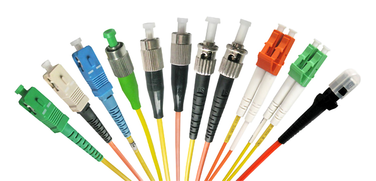
Troubleshooting plays a vital role in ensuring the reliability of fiber optic patch cord connections. Challenges such as bending loss, splice loss, and insertion loss frequently disrupt performance. Loose connectors, overbending, and environmental factors further complicate network stability. Proactive maintenance, especially for components like duplex fiber optic patch cords or armoured fiber optic patch cords, minimizes risks. Regular inspections of SC patch cords and LC patch cords help detect issues early, preventing costly downtime.
Key Takeaways
- Clean fiber optic connectors often to keep them dirt-free. This easy task helps reduce signal problems and keeps the network working well.
- Check connectors and cables often for damage or wear. Finding problems early can stop big issues and keep connections strong.
- Use the right tools to align connectors during setup. Proper alignment improves signal flow and makes the network work better.
Dirty End Faces in Fiber Optic Patch Cords
Causes of Contamination
Contamination on fiber optic patch cord end faces is a leading cause of signal degradation. Dust particles, fingerprint oils, and moisture often accumulate on connectors, obstructing the signal path. Even particles as small as 5-6 microns can disrupt transmission. Electrostatic charges generated by friction attract dust to the connector end face, further worsening the issue. These contaminants not only block light but also alter the refractive index, causing chromatic aberration and insertion loss. Over time, scratches or cracks may develop, leading to permanent damage and reduced performance.
Effective Cleaning Techniques
Proper cleaning techniques are essential to maintain the performance of fiber optic patch cords. Wet cleaning, using pre-soaked wipes or solvents, effectively removes stubborn residues. Lint-free wipes, combined with a gentle wiping motion, prevent scratches. For confined spaces, swabs or sticks are ideal. Click-to-clean tools offer quick and efficient cleaning in high-density environments. A wet-to-dry cleaning process, where a solvent is applied and wiped from wet to dry areas, ensures thorough removal of contaminants. Advanced solutions, such as oxygenated solvents, neutralize static charges and evaporate quickly, leaving no residue.
| Cleaning Technique | Description |
|---|---|
| Wet Cleaning | Uses pre-soaked wipes or solvents to dissolve contaminants. |
| Lint-Free Wipes | Removes particles without scratching the surface. |
| Click-to-Clean Tools | Deploys cleaning tape for quick cleaning in dense setups. |
| Wet-to-Dry Cleaning | Combines solvent application with a dry wipe for effective cleaning. |
When to Replace Damaged Connectors
In some cases, cleaning may not restore the functionality of a fiber optic patch cord. Deep scratches, pits, or cracks on the connector end face indicate irreversible damage. If cleaning fails to improve performance or if insertion loss persists, replacing the connector becomes necessary. Regular inspections help identify such issues early, preventing further network disruptions.
Misalignment in Fiber Optic Patch Cord Connections
Causes of Connector Misalignment
Connector misalignment is a frequent issue in fiber optic systems. It occurs when the optical fiber cores fail to align correctly, leading to high reflection and insertion loss. Common causes include incomplete connector insertion, poor end-face geometry, or guide pin failure. Misalignment can also result from improper handling during installation or maintenance. Splice issues, though less common, may also contribute to alignment problems. These challenges disrupt signal transmission, reducing the overall efficiency of the network.
Alignment Tools and Techniques
Proper alignment tools and techniques are essential for resolving misalignment issues. Ferrule alignment sleeves help ensure precise core alignment by holding connectors securely in place. Visual fault locators (VFLs) are effective for identifying misaligned connections by emitting a red laser light through the fiber. Technicians can also use optical time-domain reflectometers (OTDRs) to detect and analyze alignment errors. For manual adjustments, alignment fixtures and microscopes provide the precision needed to achieve optimal core positioning. Regular calibration of these tools ensures consistent performance.
Ensuring Proper TX and RX Strand Alignment
Maintaining correct TX (transmit) and RX (receive) strand alignment is critical for uninterrupted communication. Technicians should verify that the TX strand of one connector aligns with the RX strand of the corresponding connector. Labeling cables and connectors minimizes the risk of cross-connections. During installation, following the manufacturer’s guidelines ensures proper alignment. Routine inspections and testing help identify and correct any misalignment before it impacts network performance. These practices enhance the reliability of fiber optic patch cord connections.
Detecting and Preventing Cable Faults
Common Types of Cable Faults
Fiber optic cables are prone to several types of faults that can disrupt network performance. These include:
- Loss: Signal attenuation caused by poor connections or damaged cables.
- Contamination: Dust or debris on connectors leading to signal degradation.
- Breaks: Physical damage to the cable, often from improper handling.
- Scratches: Surface damage on connectors that affects light transmission.
- Faulty connections: Loose or improperly installed connectors.
- Bends: Excessive bending that exceeds the cable’s minimum bend radius, causing signal loss.
Understanding these common issues helps technicians identify and address problems efficiently.
Tools for Identifying Faults
Technicians rely on specialized tools to detect and diagnose cable faults. Commonly used tools include:
- Visual fault locators (VFLs): Emit a red light through the fiber to reveal breaks, bends, or poor connections.
- Fiber optic testers: Measure signal strength and troubleshoot network issues.
- Optical time domain reflectometers (OTDRs): Analyze the entire fiber link to pinpoint faults.
- Fiber optic microscopes: Inspect connector surfaces for contamination or scratches.
- Power meters and light sources: Measure optical power levels to detect signal loss.
These tools provide accurate diagnostics, enabling quick resolution of fiber optic issues.
Tips to Avoid Cable Damage
Preventing cable faults begins with proper handling and installation practices. Follow these tips to maintain the integrity of fiber optic cables:
- Handle cables with care to avoid physical damage.
- Use high-quality cables and connectors for long-term reliability.
- Avoid overbending cables during installation to maintain signal integrity.
- Clean connectors regularly to prevent contamination.
- Pull cables by their strength members, not the jacket, to prevent internal damage.
By implementing these practices, technicians can reduce the risk of faults and ensure the reliable performance of fiber optic patch cords.
Troubleshooting Insertion Loss in Fiber Optic Patch Cords
Understanding Insertion Loss
Insertion loss refers to the reduction in optical power as light passes through a fiber optic system. It is a critical parameter that directly impacts the performance of fiber optic networks. For instance:
- Multimode fiber experiences only about 0.3 dB (3%) signal loss over 100 meters, while Category 6A copper cables lose approximately 12 dB (94%) over the same distance.
- High-speed applications like 10GBASE-SR and 100GBASE-SR4 have strict insertion loss limits of 2.9 dB and 1.5 dB, respectively, over 400 meters.
Loss budgets, calculated during the design phase, ensure compliance with these specifications, maintaining optimal network performance.
| Application | Maximum Insertion Loss | Distance |
|---|---|---|
| 10GBASE-SR | 2.9 dB | 400 meters |
| 100GBASE-SR4 | 1.5 dB | 400 meters |
| Multimode Fiber | 0.3 dB (3% loss) | 100 meters |
Testing for Signal Loss
Accurate testing is essential to identify and address insertion loss in fiber optic patch cords. Common methods include:
| Testing Method | Description |
|---|---|
| Optical Loss Test Sets (OLTS) | Measures total light loss in a fiber optic link under simulated network conditions. |
| Optical Time-Domain Reflectometer (OTDR) | Sends light pulses to detect faults, bends, and splice losses by analyzing scattered or reflected light. |
| Visual Fault Locator (VFL) | Uses a visible light laser to identify breaks and tight bends in the fiber optic cable. |
Technicians often use OLTS for precise measurements, employing a light source at one end and a power meter at the other. Encircled flux (EF) launch conditions minimize measurement uncertainty, ensuring reliable results.
Minimizing Insertion Loss
Reducing insertion loss requires a combination of careful planning and proper installation techniques. Effective strategies include:
- Polishing and cleaning fiber ends to remove contaminants.
- Minimizing end gaps during connections to reduce signal loss.
- Connecting fibers of the same size to avoid mismatches.
Additionally, accurate insertion loss budgeting during the design phase ensures that the total loss remains within acceptable limits. Regular testing with optical power meters verifies compliance with these budgets, maintaining the performance of the fiber optic patch cord network.
Addressing Connector Wear in Fiber Optic Patch Cords
Signs of Worn Connectors
Worn connectors in fiber optic systems often exhibit clear signs of degradation. Contamination on the ferrule, scratches on the connector end face, and poor fiber alignment are common indicators. These issues can block or scatter light signals, leading to significant performance loss. Dirty connectors, for instance, may cause insertion loss to exceed the recommended threshold of 0.3 dB, while return loss may drop below 45 dB, compromising signal strength. Technicians frequently use tools like Visual Fault Locators (VFLs) and Optical Time Domain Reflectometers (OTDRs) to detect these problems. Connector loss, typically ranging from 0.25 to over 1.5 dB, often results from dirt, improper installation, or misalignment.
Maintenance to Prolong Connector Life
Proper maintenance is essential to extend the lifespan of fiber optic connectors. Regular cleaning of connector ends removes dust and oils, which account for 85% of attenuation loss issues. Visual inspections help identify physical damage early, preventing further deterioration. Scheduling periodic signal testing ensures consistent performance and minimizes downtime. Maintaining cleanliness and conducting routine checks are proven strategies for reducing wear and prolonging the life of fiber optic patch cords.
Replacing Worn or Damaged Connectors
When connectors show visible damage, such as corrosion or deep scratches, replacement becomes necessary. Technicians should follow a systematic approach:
- Conduct a visual inspection to identify damage or contamination.
- Perform performance tests, including contact resistance and insulation resistance checks.
- Evaluate mechanical components for wear or misalignment.
- Replace damaged parts promptly to restore functionality.
- Reassemble connectors according to manufacturer specifications.
For complex issues, consulting professionals ensures proper resolution. Keeping a record of the diagnosis process helps prevent future problems and ensures the reliability of the fiber optic patch cord network.
Avoiding Installation Errors in Fiber Optic Patch Cord Setups
Common Installation Mistakes
Installation errors can significantly impact the performance of fiber optic systems. Recent surveys highlight several common mistakes:
- Single Strand Fiber Device Must Be Used in Pairs: Mismatched transceivers often lead to installation failures.
- Don’t Use Single-Mode Fiber over Multimode Fiber: Incompatible fiber types result in dropped packets and errors.
- Understand All Kinds of Fiber Connectors First: Proper knowledge of connector types ensures accurate installations.
- Connector Links and Splice Times Also Affect: Excessive connectors and splices increase signal loss.
Additionally, improper cleaning procedures and incorrect cable pulling techniques frequently cause connectivity issues. Dirty fiber endfaces alone account for 85% of attenuation loss, emphasizing the importance of cleanliness during installation.
Importance of Proper Training
Proper training equips technicians with the skills needed to avoid installation pitfalls. Training programs focus on cleaving and splicing techniques, ensuring precise connections. Technicians also learn to use tools like power meters and visual fault locators, which help identify and resolve issues during installation. Without adequate training, errors can lead to costly downtime, especially in data centers. Safety training further minimizes risks, ensuring a secure working environment for installers.
Best Practices for Installation
Adhering to best practices ensures reliable fiber optic patch cord setups. The following table outlines validated practices and their benefits:
| Best Practice | Evidence |
|---|---|
| Cleanliness | Dirty fiber endfaces account for 85% of attenuation loss issues. |
| Proper Testing Protocols | Bi-directional OTDR testing and end-to-end insertion loss testing improve accuracy. |
| Minimizing Bend Radius | Respecting the minimum bend radius prevents internal glass fiber damage. |
| Managing Pulling Tension | Avoiding excessive tensile strength maintains cable integrity. |
Pre-installation planning and comprehensive site surveys also prevent common challenges. Documenting test results for all installed fiber segments ensures accountability and simplifies future troubleshooting.
Additional Troubleshooting Tips for Fiber Optic Patch Cords
Checking for Disconnected Cables
Disconnected cables are a common issue that can disrupt network performance. Technicians should begin by visually inspecting all connections to ensure cables are securely plugged into their respective ports. Loose or improperly seated connectors often cause intermittent signal loss. Using a Visual Fault Locator (VFL) can help identify disconnected or broken cables by emitting a visible red light through the fiber. This tool highlights any breaks or disconnections, allowing for quick resolution. Regularly labeling cables also minimizes the risk of accidental disconnections during maintenance.
Inspecting Patch Panels for Faulty Connections
Patch panels play a critical role in organizing and managing fiber optic connections. Faulty connections within these panels can lead to signal degradation or complete network failure. Technicians should inspect patch panels for signs of wear, such as bent or damaged connectors. A thorough visual inspection under magnification can reveal scratches or contamination on connector surfaces. Tools like Optical Power Meters (OPMs) and Optical Time Domain Reflectometers (OTDRs) are invaluable for testing signal strength and pinpointing faults within the patch panel. Routine maintenance ensures patch panels remain in optimal condition, reducing the likelihood of performance issues.
Ensuring Adequate Transmitting Power
Adequate transmitting power is essential for maintaining a reliable fiber optic network. Technicians should measure signal power at various points using an Optical Power Meter to identify any losses or degradations. Insertion loss testing can further assess the impact of connectors and splices on signal strength. Preventive measures, such as cleaning connectors with lint-free wipes and cleaning fluid, help maintain optimal power levels. Staying informed about advancements in fiber optic technology ensures the use of efficient equipment, enhancing overall network performance.
Tip: Regularly updating maintenance procedures and adhering to industry standards can significantly improve the reliability of fiber optic patch cord connections.
Effective troubleshooting ensures the reliability of fiber optic patch cords. Regular inspections, including visual checks and connector cleaning, maintain optimal performance. Proper handling prevents contamination and damage, ensuring uninterrupted signal transmission. Dowell offers high-quality fiber optic solutions, trusted for their durability and precision.
Key Practices:
- Cleanliness and proper end-face geometry
- Adherence to industry standards
FAQ
What is the most common cause of fiber optic patch cord failure?
Contamination on connector end faces is the leading cause. Dust, oils, and debris block light transmission, resulting in signal loss and degraded performance.
How often should fiber optic connectors be cleaned?
Technicians should clean connectors before every connection or test. Regular cleaning prevents contamination, ensuring optimal signal transmission and reducing the risk of network issues.
Can damaged fiber optic cables be repaired?
Minor damage, like scratches, can sometimes be polished. However, severe damage, such as breaks, typically requires cable replacement to restore functionality.
Tip: Always inspect cables and connectors during routine maintenance to identify potential issues early.
Post time: Mar-29-2025